After eight years of usage of my KR-400 (VHF antennas) and my KR-600 (HF antennas) both direction indicators started flickering at certain positions and an examination results in a failure of the potentiometer. I ordered spare parts from our german dealer (UKW Berichte) and started repair. During this repair I found out that there are some surprises in the rotator body. So I decided to write down my experience in this document to help others.
Before starting, you will need these tools (table under construction):
| tool | size |
|---|---|
| Allen-Type / set-screw | very small (1 mm) ? |
| box-end wrench / open-end wrench | 10 / 11 ? |
| Phillips screwdriver | PH2 ? |
I turned the rotator to its 'middle position', beaming north direction. So you won't get in trouble while re-assembling the rotator, neither with the end-position lever nor with the potentiometer setting.
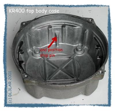
When you take of the top case, you'll see the stop pin for the end-position lever.
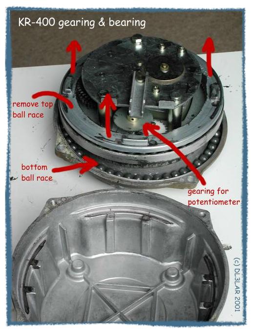
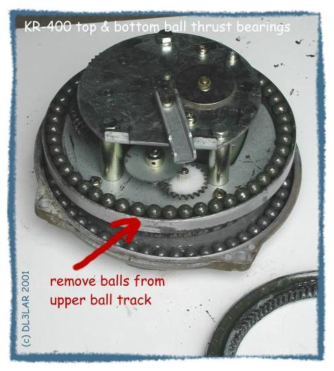
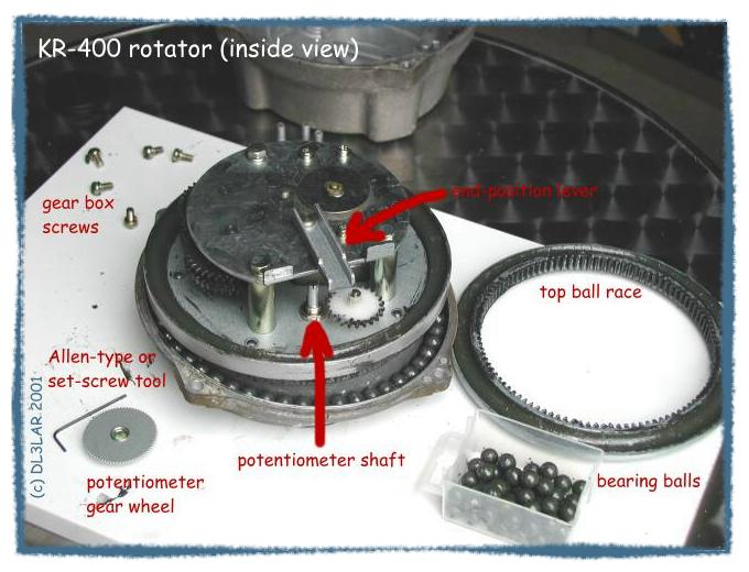
Before you can unmount the gear box from lower rotator body, you have to remove the balls from the upper ball track as shown below. Don't lose any of the balls !
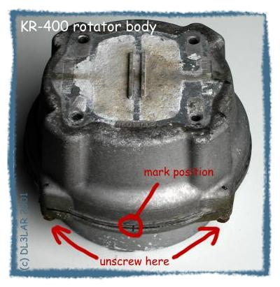
There are five Phillips screws that needed to be unscrewed.
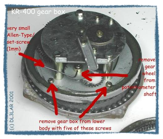
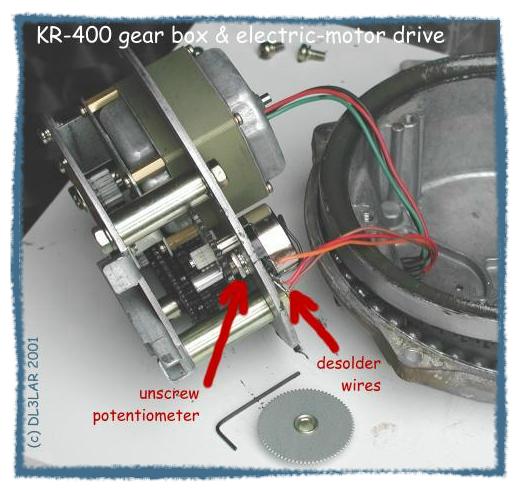
Now you can take out the gear box and the electric motor drive. Unscrew the potentiometer as shown below and desolder the wires. Remember the order of the wires (make a note).
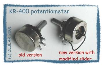
Replace the old potentiometer with the new part. In my case, the old one differs mainly in the open frame and the new wire connection to the slider.
The assembly of the rotator is carried out in reverse order. You have to turn the potentiometer to its middle position before you fasten the gear wheel with the set-screw / Alley-type. I used an ohmmeter for aligning.
Next fasten the five gear box screws with the Phillips screw-driver. I used an electrical screwdriver to apply the nearly the same torque to the screws. A torque screw-driver will be better.
Return all balls to the upper ball track and carefully add the upper ball race. It's a little bit difficult to fix it into the potentiometer gear and simoultaneous into the main gear from the motor. Take some care of the direction: the end position stop pin of the top body case should be opposite to the end-position lever, so that the rotator is able to turn 180° in each direction.
If everything seems to be okay, close the rotator body by mounting the top and lower case. Again, you should apply the same torque to all four screws by using a torque wrench.
Congratulations ! Your direction indicator should be okay again.
If you have any comments on this guide, I would be very pleased about a short note.
73, DL3LAR Email to mail @ dl3lar.de